

DTI Quality Control - Part 2: Tensor fitting
0,0,0,0,0,0,1000,1000,1000,1000,1000,1000,1000,1000,1000,1000,1000
Your b-vector are the gradient directions that you collect, often predetermined by the scanner depending on how many total directions you choose to collect. A b-vector file will look something like this (shortened version):
 |
| b-vectors |
The b-vectors consist out of 3 separate vectors (x, y, z) for each direction acquired. A program like fsl2scheme (more info here) will be able to combine the b-values and b-vectors into a scheme file. Together looking something like this (note that there are 4 b0 slices visible, while the scheme file only shows 1 b0):
 |
| Scheme file, next to diffusion volumes |
If you run a eddy correction it is advisable to correct your scheme file for the induced movement of each volume after registration. Here are a couple of resources to help you with this:
http://onlinelibrary.wiley.com/doi/10.1002/mrm.21890/abstract
https://github.com/bernardng/codeSync/blob/master/dMRIanalysis/rotatebvecs
https://www.jiscmail.ac.uk/cgi-bin/webadmin?A2=FSL;3c23f260.0903
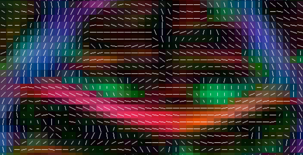
After running the tensor fitting command you will have to check if the vectors were applied correctly. In the below examples we are using Camino's pdview, but you can use any program that allows you to view the tensors. You should check the axial, coronal and sagittal views. As a reference the corpus callosum can be used, the tensors should follow the shape of the corpus callosum (in red) in a fluid motion, as in the examples below:
 |
| Axial view |
 |
| Coronal view |
 |
| Sagittal view |
EXAMPLES OF WRONG ORIENTATION:
Notice the tensor orientations in corpus callosum (red area)
 |
| Wrong orientation |
Fix it by adjusting the scheme file:
There are multiple options to correct the scheme file in the fsl2scheme command:
- add -usegradmod(usually when error pops up)
- add -flipx
- add -flipy
- add -flipz
- or any combination of the above, eg. as used in the example above: fsl2scheme -bvecfile bvecs.txt -bvalfile bvals.txt -flipx -flipy -usegradmod prefix.scheme
EXAMPLE OF WRONG COLOR:
Notice the blue corpus callosum
 |
| Wrong orientation |
Fix it by adjusting the b-vector table:
- In the bvecs text file, swap the x and z row with the directions.
- And in this specific case: fsl2scheme -bvecfile bvecs_zx.txt -bvalfile bvals.txt -flipx -flipz -usegradmod prefix.scheme
ANOTHER EXAMPLE:
Notice the green corpus callosum |
| Wrong orientation |
Fix it by adjusting the b-vector table:
- In the bvecs text file, swap the x and y row.
- And in this specific case: fsl2scheme -bvecfile bvecs_yx.txt -bvalfile bvals.txt -usegradmod prefix.scheme
x - Red
y - Green
z - Blue
Remember:
y - Green
z - Blue


